
Featured Precision Flow Control & Air Release Valve Series
Explore our core catalog of heavy-duty industrial valves engineered for municipal water networks, hydraulic surge protection, power generation, and chemical process pipelines. Every valve is rigorously pressure-tested to meet international ISO, DIN, BS, and API benchmark standards.
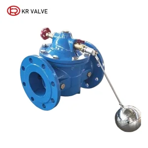
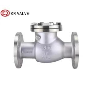
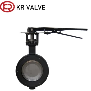
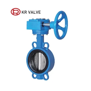
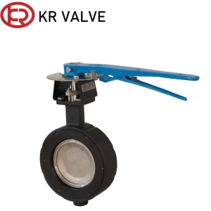
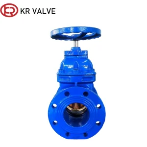
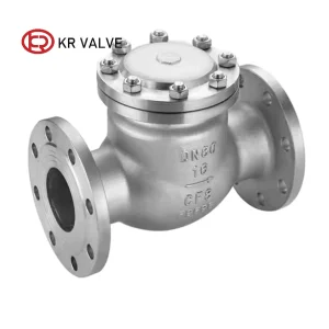
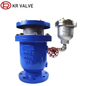
Executive Engineering Summary: The Physics of Entrapped Air in Pressurized Conduits
In pressurized municipal water networks, industrial raw-water transmission mains, and sewage conveyance systems, entrapped air represents one of the most critical threats to hydraulic efficiency and structural integrity. Undissolved gas pockets naturally accumulate at elevated pipeline profiles, localized high points, and long horizontal stretches. Left unmitigated, these air pockets behave like elastic cushions under compression, causing severe flow restrictions, head loss amplification, pump efficiency degradation, and catastrophic hydraulic transients (water hammer spikes).
According to fluid thermodynamic governing principles, the behavior of air in pressurized liquid media is dictated by Boyle’s Law ($P_1 V_1 = P_2 V_2$) and Henry’s Law regarding gas solubility. When a main pipeline is initially charged with water, vast volumes of ambient air must be rapidly displaced through large orifices to prevent pressure buildup. Conversely, during sudden pump shut-offs, power failures, or main line drainages, sub-atmospheric negative pressures develop. Without rapid vacuum-breaking air intake, thin-walled ductile iron, steel, or HDPE pipes risk structural collapse.
Key Information Gain Insight for Engineering Specifiers
Traditional single-orifice air release valves frequently suffer from "premature closing" during high-velocity air exhaust—where the dynamic pressure of escaping air lifts the internal float disc prematurely before all air is evacuated. Modern custom air relief valve designs, such as the CARX High-Speed Compound Release Series, integrate two-stage kinetic anti-slam float assemblies and non-choking orifice geometries. This engineering innovation ensures continuous, high-volume venting up to sonic air velocity ($\sim M 1.0$), eliminating dynamic choking and surge spikes during initial pipe filling.
Triple-Function Mechanics & Kinetic Dynamics of Custom Air Relief Valves
Custom air relief valves operate across three distinct operational phases in hydraulic pipeline lifecycles. Selecting the appropriate valve configuration requires a comprehensive understanding of internal float buoyancy, dynamic pressure differentials, and orifice cross-sectional scaling.
1. High-Speed Kinetic Exhaust
During initial pipeline charging, massive volumes of air are expelled through the primary large orifice ($DN50$ to $DN300$). The float remains fully suspended in the open position until water fills the valve chamber, at which point net hydrostatic buoyancy forces elevate the float, sealing the primary seat without water spillage.
2. Pressurized Automatic Venting
Under normal working pressures ($PN10$ to $PN40$), dissolved air separates from liquid solution and accumulates at the top of the valve dome. As gas volume increases, water level drops, lowering the secondary micro-orifice float. This opens a small precision nozzle ($1.5\text{mm}$ to $3.0\text{mm}$), continuously releasing entrapped gas under full line pressure.
3. Vacuum Breaking & Re-entry
When pipeline drainage occurs or a power outage causes sudden pump shutdown, negative pressure causes the buoyant float to drop instantaneously. The large orifice unseals, allowing atmospheric air to rush inward at high volumetric flow rates, neutralizing vacuum conditions and protecting pipe walls from buckling.
Engineering Specification & Performance Matrix
| Valve Type Series | Nominal Sizes | Pressure Ratings | Primary Material Standard | Sealing & Float Material | Core Application Domain |
|---|---|---|---|---|---|
| CARX Compound Air Relief | DN50 – DN300 (2" – 12") | PN10, PN16, PN25, PN40 | Ductile Iron GGG40 / GGG50, WCB | SS304 / SS316 Float + EPDM Seat | Municipal Water Trunk Lines, Pump Stations |
| Single Orifice Auto Release | DN15 – DN50 (1/2" – 2") | PN10, PN16, PN25 | Ductile Iron, SS304, Stainless CF8 | Polypropylene Float + NBR / Viton | High-rise Building HVAC, Small Branch Lines |
| Anti-Slam Air Relief Valve | DN50 – DN400 (2" – 16") | PN16, PN25, PN40, Class 150/300 | Ductile Iron, WCB, CF8M Stainless | Dual Stainless Floats + Surge Disc | Long-distance Transmission, Raw Water Lines |
| Wastewater Air Relief Valve | DN50 – DN200 (2" – 8") | PN10, PN16 | Ductile Iron GGG40 with Epoxy Coating | Elongated Body + Lower Stainless Float | Sewage Mains, Effluent Pumping Lines |
OEM Customization & Advanced Metallurgical Specifications
Global EPC contractors and municipal utility authorities often require customized air release valve builds to withstand aggressive soil chemistries, desalinated seawater, industrial chemicals, or severe operating temperature swings. Our modern manufacturing plants deliver complete OEM flexibility, from pattern making and metallurgy selection to specialized surface protection.
Body Metallurgy & Casting
Option of High-Tensile Ductile Iron (EN-GJS-400-15 / ASTM A536 65-45-12) for cost-effective resilience, Carbon Steel WCB for high-pressure oil/gas lines, and Stainless Steel (CF8/CF8M/Super Duplex 2205) for extreme chloride/seawater desalination duties.
Internal Float & Trim Components
Floats are precision-machined from SS304/SS316 stainless steel spheres or high-density polypropylene polymers engineered with internal reinforcing ribs. This design prevents float collapse under high hydraulic shock pressure up to 60 bar.
Anti-Corrosion FBE Coating
Electrostatic application of Fusion-Bonded Epoxy (FBE) powder at a thickness of 250 µm to 350 µm inside and out. Fully compliant with WRAS, NSF-61, and EN 14901 standards for safe drinking water compatibility and 50+ years of underground longevity.
China Supply Chain Advantages & Manufacturing Capability
Operating from China's premier valve industrial hubs—such as the Tianjin and Zhejiang valve manufacturing clusters—gives overseas procurement partners a decisive competitive advantage in cost structure, production lead times, and scaled quality control. Our integrated manufacturing supply chain eliminates intermediate broker markups, streamlining raw material procurement, foundry casting, precision CNC machining, testing, and export clearance under one centralized quality management system.
Every air relief valve unit produced undergoes a rigorous two-stage hydrostatic and pneumatic test protocol prior to packaging:
- High-Pressure Shell & Seat Test: Hydrostatic shell test performed at 1.5 times nominal pressure rating ($1.5 \times PN$) and seat seal test at $1.1 \times PN$ according to API 598 and EN 12266-1.
- Low-Pressure Air Sealing Test: A critical 0.2 bar ($3\text{ psi}$) low-pressure air tightness test to ensure that the soft EPDM seat achieves a bubble-tight seal even under minimal head pressures—eliminating annoying low-pressure leaks common in low-tier air valves.
- Spectrographic Material Analysis: Optical emission spectrometry verification on every batch of raw ductile iron and stainless steel castings to guarantee chemical composition and tensile strength compliance.
Global Procurement Standards & Localized Compliance Guarantee
Navigating international trade and engineering standards requires strict adherence to regional design codes. Our custom air relief valves and pipeline accessories are fully certified and engineered to match global project requirements across Europe, the Americas, the Middle East, and Southeast Asia.
American Standards (AWWA / ANSI)
Designed in accordance with AWWA C512 (Air Release, Air/Vacuum, and Combination Air Valves for Waterworks) and flanged to ASME B16.1 / B16.5 Class 150/300 standards. Certified NSF/ANSI 61 compliant for potable water safety.
European & British Standards (EN / BS)
Manufactured to EN 1074-4 (Valves for Water Supply - Air Valves) and face-to-face dimensions per EN 558 series. Flange drilling standard per EN 1092-2 PN10, PN16, PN25, PN40. WRAS approved soft seat materials.
Comprehensive Technical Documentation
Supplied with complete inspection dossiers: EN 10204 3.1 Material Test Certificates (MTC), NDT radiograph reports, coating thickness reports, hydro-test charts, Certificate of Origin (Form E/CO), and 3D CAD step files for engineering integration.
Localized Application Scenarios & Piping System Integration
Correct placement of air relief valves within hydraulic network schematics is just as vital as valve sizing. Our engineering field teams provide detailed surge analysis support and localized positioning recommendations across key industrial sectors:
Municipal Water Trunk Lines
Positioned at high summits, long horizontal pipe runs (every 500–800 meters), and downstream of booster pump stations to ensure continuous air discharge during water main charging and protection against column separation.
Agricultural Irrigation Mains
Installed at filtration headers and pivot riser branches to rapidly exhaust air when pumps start, eliminating drip line rupture and preventing vacuum collapse when systems drain during non-irrigation cycles.
Desalination & Seawater Conveyance
Engineered with Super Duplex 2205 or Nickel Aluminum Bronze internal floats and rubber-lined body chambers to withstand high salinity corrosion, bio-fouling, and cavitation wear in RO plant intake lines.
Complete Industrial Valve & Flow Control Portfolio
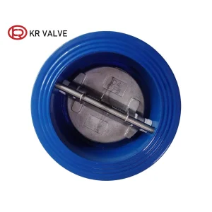
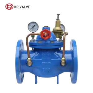
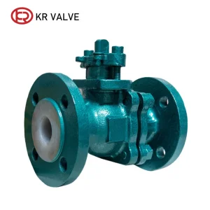
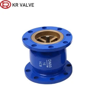
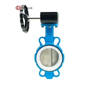
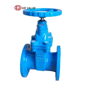
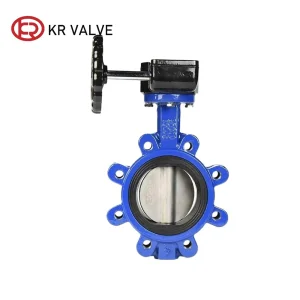
Discover additional high-performance valve series designed for specialized throttling, non-return check isolation, pressure regulation, and corrosive media isolation.
Industry Trends & Next-Generation Valve Innovation
The global industrial valve manufacturing market is undergoing a rapid technological evolution driven by digitalization, smart municipal water grid adoption, strict ESG sustainability metrics, and advanced computational fluid dynamics (CFD) modeling.
IoT-Enabled Smart Air Valves
Integration of wireless micro-transducers and acoustic sensors inside the air valve dome allows real-time telemetry tracking of internal air pocket volume, venting frequency, and transient surge pressures—feeding live data into SCADA municipal monitoring networks.
Multi-Stage Anti-Slam Technology
Advanced surge cushioning mechanisms now incorporate secondary spring-loaded throttling discs that automatically choke air discharge when water approaches the seat at high speed—limiting water hammer pressure spikes to safe, non-destructive thresholds.
Eco-Friendly Low-VOC Coatings
Transition towards PFAS-free elastomer seals and 100% solvent-free electrostatic epoxy powders reduces carbon footprint during valve production while extending field service life past 50 years without recoating.
Comprehensive Technical Q&A: Engineering & Sizing FAQ
Detailed technical answers to common queries raised by hydraulic engineers, utility project managers, and industrial procurement specialists.
Air relief valve sizing requires analyzing two distinct operational states: 1) Initial pipeline filling (air exhaust) and 2) Pipeline draining or collapse (vacuum breaking). The required kinetic air discharge capacity ($Q_{air}$ in $\text{m}^3/\text{hr}$) is determined by calculating maximum filling velocity ($V_{fill} \approx 0.3\text{ to } 0.6 \text{ m/s}$) multiplied by pipe cross-sectional area, maintaining differential pressure across the valve below $0.3\text{ bar}$ ($4.3\text{ psi}$) to prevent premature float closure.
A single-orifice automatic air release valve features a small nozzle ($1.5\text{mm} - 3\text{mm}$) designed strictly to bleed small amounts of pressurized air accumulated during continuous operation. A compound combination air valve (such as the CARX series) integrates both a large kinetic orifice ($DN50 - DN300$) and a small automatic orifice into a single valve body—enabling high-volume air venting during pipe filling, high-volume air intake during draining, and continuous pressurized gas purging.
High line pressure easily forces rubber seats tight against metal orifices. However, under low static head conditions (such as elevated pipe crests or low-flow periods), low-quality air valves frequently seep water due to insufficient mechanical seating force. Standard 0.2 bar ($3\text{ psi}$) factory tightness testing ensures the float and resilient EPDM seal achieve zero-leak closure even at minimal working pressures.
During rapid air exhaust, water rushing behind the air column can slam into the float disc with destructive force, generating pressure spikes up to 50 bar. An anti-slam mechanism introduces a secondary spring-loaded throttling disc that restricts air discharge velocity when water reaches the valve chamber, decelerating the water column smoothly before final seat contact and dampening hydraulic shock.
We provide comprehensive OEM customization including specialized body alloys (Cast Steel WCB, SS304, SS316, Super Duplex), high-temperature Viton or NBR seals, non-standard flange drilling (EN 1092-2, ANSI B16.5, JIS 10K/20K, BS4504), tailored FBE coating colors (RAL 5005, RAL 5015, RAL 3000), customized stainless nameplates, and third-party witness inspection protocols (SGS, TUV, Bureau Veritas).